 Home
Home About Us
 Products
 Facilities
 Explore
 Contact Us
Where The Magic Unfolds
Our manufacturing process is optimized at each step to give you the most reliable product with the most efficient use of our resources. Our advanced technical setup proves to be significantly effective in reducing costs, improving product performance and value.
Mack Springs incorporates latest technology that makes our products shine in the market for its durability and finishing. We believe in efficient production to achieve the highest quality products.
The manufacturing of commercial vehicle springs has always been a forte of Mack Springs. We have years of expertise in the Automobile industry for which we have been praised & recognized by the expertise and industry-level skills and we are proud to be one of the market leaders in the global market, manufacturing springs for companies in USA, Europe, Africa, Middle East and Asia.
We manufacture all types of springs, and we specialize in manufacturing Multileaf and Parabolic Springs for commercial vehicles (LCVs and HCVs) in India. We are committed to achieving total customer satisfaction by delivering quality products, in time to adhere to the requirements specified by the customer.
Mack Springs is well-known for its production of springs for commercial heavy duty vehicles that have a long life with a perfect fitting accuracy. All our products go through a real deal production process and intense quality control testing system. We also have the capability to do value engineering of existing springs resulting in weight and cost reduction while maintaining the performance requirement.
We are constantly upgrading the technology used in the production process ensuring delivery of top quality springs for well-known automobile brands across the globe. We believe in a good team work. Hence, having right people with right skills and industry expertise has expanded the horizons for Mack Springs to do business in the global market.
Our Plant is equipped with world class testing equipment for metrology and metallurgy. Our Lab is equipped with latest testing equipments such as Hardness Testing Machine, Argon Gas based Spectrometer, and fully automatic microscope with image analyzer.
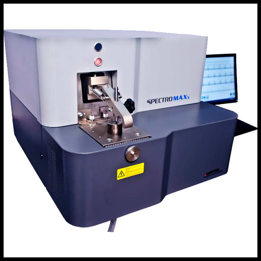
Spectrometer (Chemical Testing)
Metal analyser is used for advance elemental analysis of incoming material. It determines with high accuracy the composition of elements in spring steel, including metal analysis of Carbon, Silicon, Manganese, Chrome, Vanadium, Phosphorous, Molybdenum and Sulphur. Using Argon gas based Spectrometer you can determine 27 different constituents of non-ferrous materials in a matter of seconds.
Click here to know more.
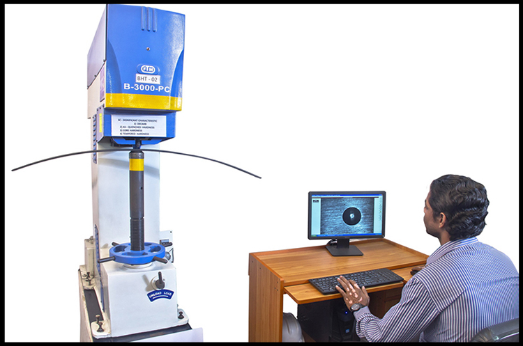
Hardness Tester
A mechanical test shows whether a material or part is suitable for its intended application by measuring properties such as Hardness. The Hardness Tester is a fully automated mechanism used to determine the hardness of material in any known scale.
Fully computerized system for Indentation measurement and display.
Accurate measurement of Brinell Hardness is done using advanced image processing technology

Microscope (Metallurgical Testing)
A wide-range of microstructure and macrostructure examinations are performed including:
Using Microscope
- Grain Size Determination
- Presence of Non-Metallic Inclusions
- Microstructure
- Decarb
The Microscope with Image Analyzer is fully automated with an inbuilt image analyzer. This machine can study the micro structure of any material and compare it with those stored in its database to ensure the exactness.
Click here to know more.
Dimensional Inspection
Dimensional inspection is performed in as per the specification.
We at Mack Spring are constantly evolving and upgrading all our technology and keeping up with the latest process so that our unique “quick-change” processes and computerized production methods are the keys to a world-class operation which is specifically suited to meet the clients’ requirements and as O.E. Specifications.
Manufacturing Process

RAW MATERIAL
On receiving the raw material, (Spring steel flats of 18 ft length) are stacked in the stockyard gradewise. Most commonly used grades are En45a, 60Si7, 65Si7, Sup9, Sup9a, Sup 11a etc. Cross Section of the steel flats ranges from 45x6mm to 120x40mm depending upon the specific customer requirements. Before processing, raw material is subjected to receiving inspection such as dimensional, chemical & metalurgical inspection. On approval it is sent for shearing operation.

SHEARING
In this operation, the leaves that constitute an assembly are cold sheared to the required lengths in the shearing machine based on the drawing provided by the customers.

PARABOLIC PROFILE ROLLING
After shearing, leaves of the Parabolic Springs are sent for parabolic profile rolling while those of Multi Leaf Springs are sent to drilling (As Multi Leaf springs do not involve parabolic profile rolling). In this operation one end of the leaf is heated in oil fired furnace. On achieving the desired rolling temperature (950 deg C) the leaf is put on to the conveyor by the walking beam furnace. The hot leaf then enters the parabolic rolling machine, where it is gripped at the cold end and rolled to the specific profile fed in the computer. The same is repeated on the other end.

DRILLING
In this operation, the leaves are drilled at the centre on all the leaves and at the ends on the specific leaves for bearing wear pads and clips depending upon the design of the springs.

EYE ROLLING
After drilling, the main leaf or the first leaf of the assembly is sent for this operation. In this operation the leaf ends are heated in oil fired furnace to 950 deg C and rolled to the specific diameter for enclosing bushes for fitment.

EYE REAMING
After Eye Rolling, the eye diameter is machined to the final size by carbide or stainless steel reamers to encompass the bushes with the desired interference fit.

END CROPPING
After drilling, the second leaf and the subsequent leaves are sent for end cropping where the leaves are heated at the ends in the oil fired furnace to 950 deg C to crop the leaves to the desired size based on the drawing.

WRAP FORMING
After cropping, the cropped second leaf is reheated to form a wrap on one end or both the ends as desired to provide protection in service on failure of first leaf.

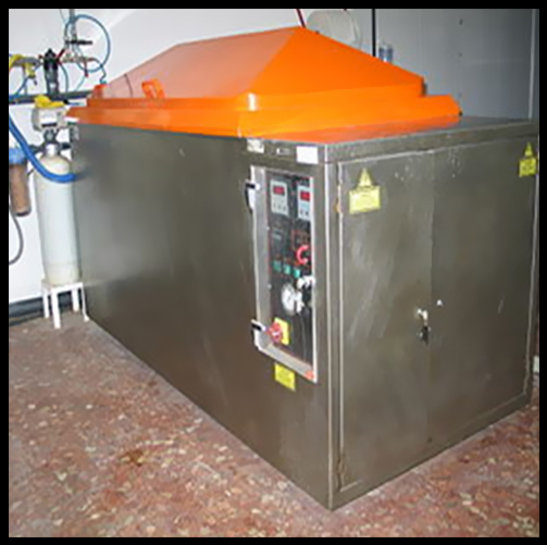
HARDENING
After all the end processing is over, the leaves are passed on to the heat treatment zone. In this the leaves are heated in the oil fired Walking Beam Furnace controlled by PID System to 920 Deg C. Depending upon the cross section of the leaf to be heat-treated, the stroke and cycle time are adjusted to ensure the total travel time in the furnace. On heating the structure of the steel is completely austenitic.

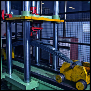
CAMBERING
After the specific total travel time, the leaves drop out at the exit of the furnace and are picked and placed on the cambering tool where the desired bend is given to the individual leaves.

QUENCHING
On providing the desired bend the cambering tool opens up, on which the leaf is picked up and quenched in the oil. The temperature of the oil tank is maintained between 70 deg C to 90 deg C to ensure correct rate of cooling. The austenitic structure changes to martensitic structure on quenching. It takes about 15 min for the leaf to come out of the quenching tank.

TEMPERING
Leaf is then placed in the tempering furnace where the temperature is maintained at 480 deg C to 520 deg C depending upon the grade of the steel being used. It takes about 1 hr 45 min for the leaf to travel through this furnace. Leaf is exposed to the hot air draft. The micro structure is changed to tempered martensite. This operation imparts toughness to the steel by reducing the hardness. The temperature of the furnace is also controlled by PID System within ± 5 deg C.

HARDNESS TESTING
Leaves coming out of the tempering furnace are tested for hardness on Brinell Hardness Testing Machine at periodic intervals to ensure that the desired hardness is achieved. The desired range of hardness is 388 to 444 BHN.

SHOT-PEENING
Leaves are then subjected to shot-peening where cut wire steel shots of 1 mm strike the tension surface to induce compressive stresses and thereby improve the fatigue life of the springs. Machine is set to the desired intensity by periodically calibrating it.
In case of Parabolic Spring’s, every individual leaf is stress-peened in which every Parabolic Leaf is deflected to flat load & held in a tray & shot-peened under load.

PRIMER APPLICATION
Leaves are provided with the initial coat of zinc chrome primer by spraying a minimum of 35 microns of thickness.

BUSHFITTING
Main leaf is fitted with the bushing as desired by hydraulic machine.

EYE GRINDING
Main leaf ends are grinded to the specified width to ensure fitment. A double wheel grinding machine is used for this purpose.

BUSH REAMING
Bush inner dia is reamed to the final size to ensure fitment of the spring eyes by means of carbide reamers mounted on the reaming machines.

CLAMP RIVETING
Clips are riveted to the leaves by means of rivets. These clips prevent the fanning of the leaves in service.

GRAPHITE APPLICATION
Tension face of all the leaves are coated with graphite paint to reduce the interleaf friction in service. Graphite application is done by means of spray gun.

ASSEMBLY
All the leaves are assembled on this machine and secured by means of centre bolt which passes through the centre of all the leaves. The desired torque is applied depending upon the size of the bolt.

SCRAGGING
The entire assembly is then subjected to a load by mounting the ends of the springs on the trolleys and applying the load at the centre by mean’s of an hydraulic machine. The load is equivalent to the 90% of the yield stress value. Scragging prevents the assembly from getting sagged in service and also relives the assembly from the internal stresses. Every assembly is subjected to scrag load 3 times in quick succession.

PARALLELISM AND TWIST CHECKING
Spring’s are checked to ensure the parallelism of eyes with respect to seat to ensure easy fitment.

CLIP FOLDING
Clips are then folded on Clamp folding machine to prevent the fanning of the leaves in service.

PAINTING
Springs are then sent for painting where the entire assembly is painted by enamel or Nitro cellulose paint by spray guns in painting booths to prevent rust in service. The total coat thickness is approx 70 microns minimum.

MARKING
Spring’s are marked by screening or stenciling for identification purpose.

PACKING
Springs are then stacked on the pallets with each layer separated by wooden ribs and then covered by air tight covers and then secured by steel strips to the pallets for dispatch.
Load Rate Testing
Load Rate is the change of load per unit deflection generally expressed in N/mm or Kg/mm. This is determined on a spring assembly mounted on rollers without center clamp and shackle & is called as unclamped Load rate. In this testing the Spring end is mounted on carriage with rollers and is free to move in the direction of datum line. Load is applied downward to the shortest leaf. The springs is compressed from no load to maximum load and released to its no load position. The loads corresponding to every 10mm deflection are noted during the compression and release of the spring. Graph of Load Vs. Deflection is plotted. Load Rate is the slope of the average of the compression and release loads.
Fatigue Testing
Fatigue Life is expressed by the number of deflection cycles a spring will withstand without failure.
Fatigue testing is an accelerated method of examining springs for design adequacy and for quality control purposes.
The Spring is clamped in the center to simulate its installation in the vehicle. The spring is loaded from 1/2g (g = Design Load) to maximum Load experienced under actual Vehicle conditions, typically 2g. Springs is cycled at a rate of between 0.5Hz to 2Hz. It is ensured that the surface temperature of the springs does not exceeds 90degree C. Fans are used to provide the cooling air. It is recommended that the fatigue setup produce at least an average of 50,000 & preferably an average of 100,000 cycles or as agreed between the supplier and purchaser.
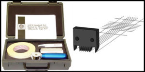
Cross Cut / Tape Adhesion Test
The cross-cut test is a method for determining the resistance of paints and coatings to separation from substrates by utilizing a tool to cut a right angle lattice pattern into the coating, penetrating all the way to the substrate.
A quick pass/fail test can be accomplished through this method. When testing a multi-coat system, determination of the resistance to separation of different layers from one another can be accomplished.
The test can be carried out on finished objects and/or on specially prepared test specimens.
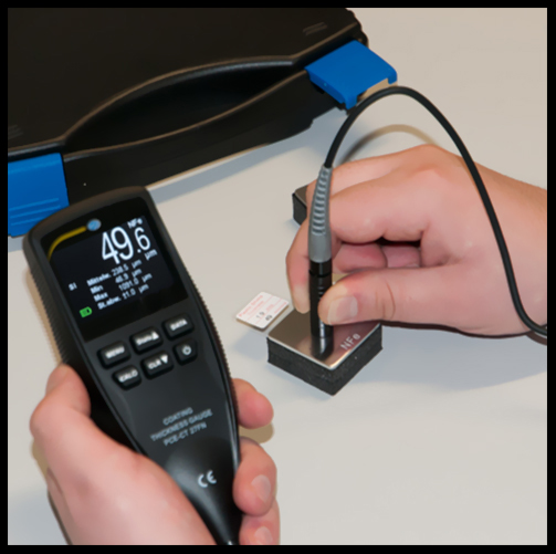
Dry Film Thickness
Dry Film Thickness (D.F.T.): The thickness of the paint film is measured in microns when it is dry. An adequate film thickness is mandatory for the success of any coating system.
Inspection
Dimensional inspection
Assesses the geometric characteristics of parts and products to assure their compliance with design specifications. Dimensional inspection verifies the accuracy of leaf spring features that can affect reliability and functionality.
Visual inspection
Visual inspection provides a means of detecting and examining a variety of surface flaws, such as corrosion, contamination, surface finish, and surface discontinuities, Part No., Camber Marking
Salt Spray Testing
The salt spray (or salt fog) test is a standardized and popular corrosion test method, used to check corrosion resistance of materials and surface coatings. Usually, the materials to be tested are metallic.
Non critical events like cracks in secondary leaves are recorded. Extension of Fatigue fracture is measured and crack starting points are well examined for Early Failure analysis.